Repairing Nikon I / M / S rangefinder cameras
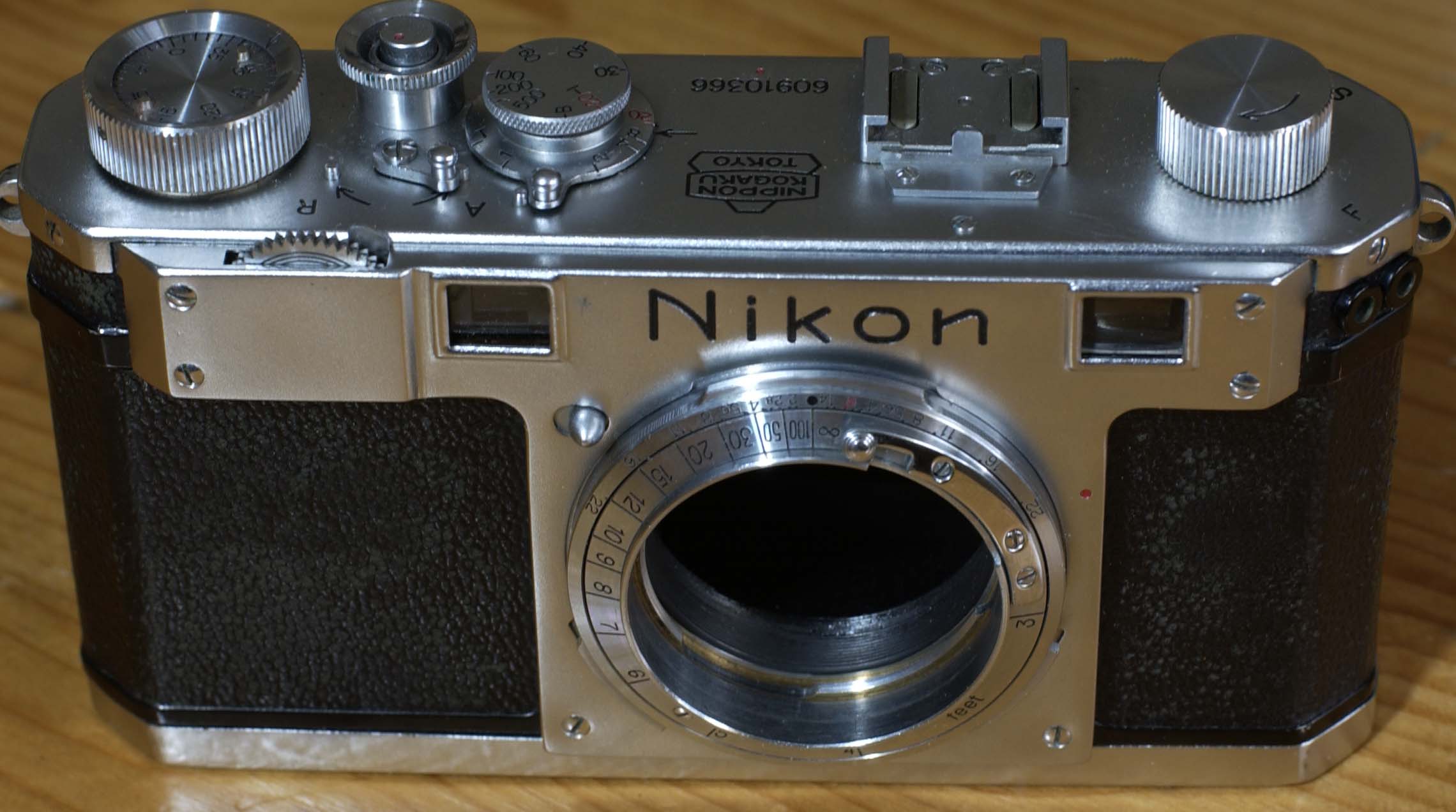
Rangefinder equipment As stated in the rangefinder chapter in this web site all Nikon rangefinder cameras (1948-1964) consist of just two designs. The Nikon I, M, MS and S use the same body, and most parts, control buttons and switches are identical. The top plate is flat, all knobs are identical, the removable back+base has two keys to open and also inside many parts are identical and thus exchangeable. Although many collectors don´t do this: keep everything original as possible.
Nikon S with a body that is almost identical to that of the Nikon I and Nikon M The Nikon S2 and later models are of a different design as the before mentioned cameras. The top plate has an elevated left part to house the larger range finder. It has a film advance lever, rewind crank and the back+base has just one key. The later models do not have a rotating shutter speed selector. Most problems are caused by the rangefinder (horizontal and/or vertical non-coincidence) and the shutter (slow-speed settings). When non-coincidence of horizontal and vertical directions is needed start with vertical adjustment. To adjust the rangefinder of the Nikon I, M, MS and S is a rather simple exercise. Set focusing mount at infinity first.
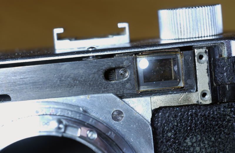
Vertical adjustment: Remove the front cover/plate (bezel) by loosening the 6 screws; be careful not to damage the focusing wheel. Left next to the range finder window is a hole (see above) with a screw and adjustment ring. Loosen the screw and adjust the rangefinder by turning the wheel (just a millimeter or so). When adjusted lock/tighten the screw. Take care of the 6 screws as the longest two belong in the holes in the bottom!
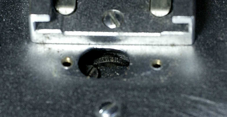
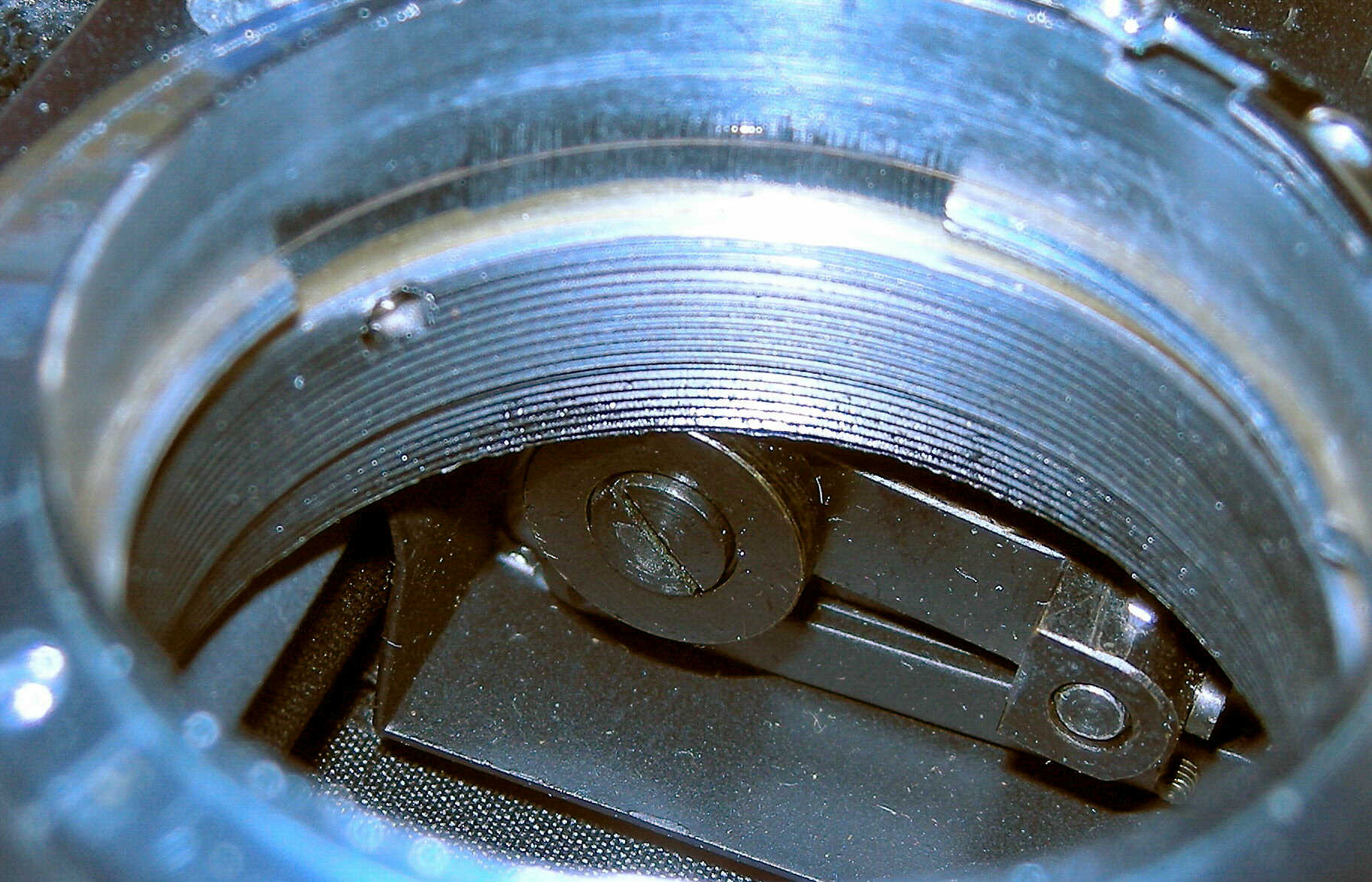
Horizontal adjustment: For the Nikon I and Nikon M the entire accessory shoe should be removed. For the Nikon S remove the little stop in front of the accessory shoe only. Under it is a hole in which a wheel (see above), secured by a set screw, can be seen. Loosen the screw and turn the wheel. When adjusted lock the set screw and put the stop back. When a lens is mounted and the lens is focused the back lens flange will press to a little wheel (see below) in the top part of the lens mount compartment.
This wheel has to move freely; if not lubricate it with less then a drip of fine oil. By pressing the wheel back and forth the rangefinder will move. If it doesn´t move the spring of the rangefinder will be damaged or (maybe) dirty. To adjust this and to clean the rangefinder inside the top plate of the camera has to be removed. Some skill is needed for this job. Leave it to a repairman if clumsiness is hereditary.
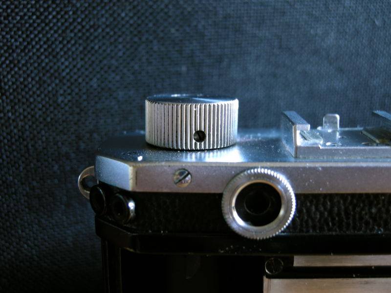
Most dials are secured by a set crew. Start with the rewind knob: loosen the set crew and unscrew the rewind knob by blocking the film cassette fork inside the camera back.
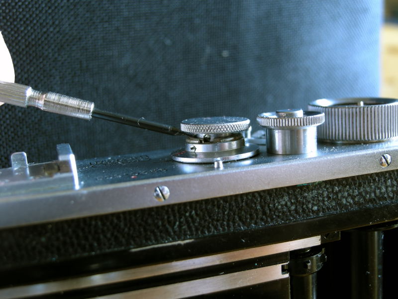
Set the slow-speed dial at 20, then lift it up and rotate it until you see the set screw. Remove that set screw and unscrew the dial (counterclockwise). The slow speed dial is secured by two set screws, which have to been unscrewed. After that the clamp spring on top of that slow speed dial should be removed. Around the shutter release button the collar should be removed by unscrewing it (ccw), then unscrew the shutter release button with a rubber stop or cork.
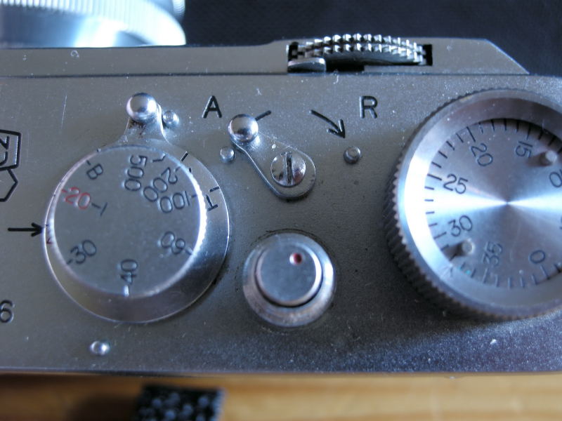
In front of the release button the A-R-knob can be removed by unscrewing its screw. It is not necessary to remove the film advance knob and accessory shoe. They come off when lifting the top plate. The top plate is fixed by 5 screws (equal length) around the body and one (smaller) screw in front of the accessory shoe.
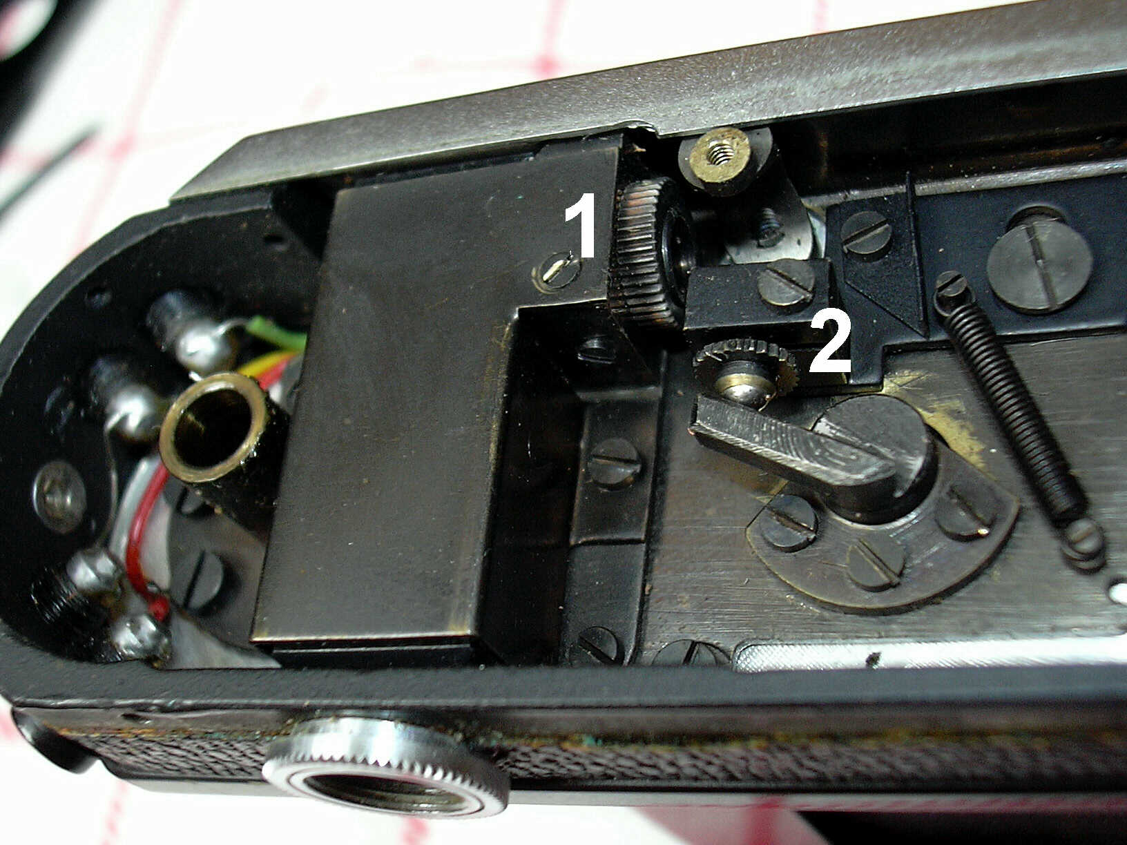
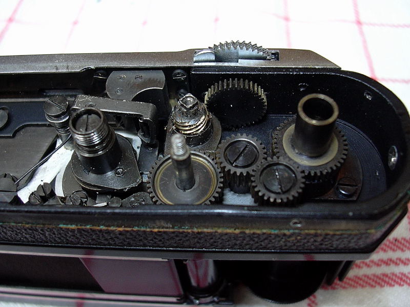
When the top plate has been removed the rangefinder system can be seen. The large cap on the left houses a (double) prism. The two wheels are the wheels with which the horizontal (2) and vertical (1) adjustments of the rangefinder can be made. Far left are the four (two pair) flash contacts.
On the right side of the camera body the film advance and shutter control parts can be seen. In front is the focusing wheel. To its left (with three screws) is the mirror of the rangefinder. To adjust the shutter you have to open the bottom of the camera body.
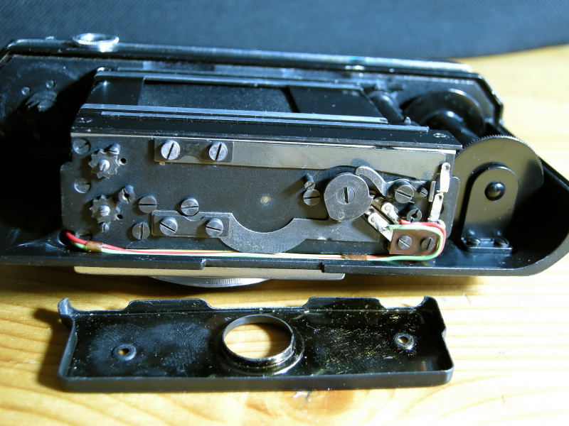
The bottom plate can be removed after removing two screws. The most important parts are the two cog wheels on the left. The cog on the top can be loosened to adjust the rear shutter curtain; the lower cog wheel holds the tension of the front shutter curtain. Both wheels are blocked by a small screw. When loosening or removing that screw the cog wheel should be hold and turned the left or right, depending on the wanted curtain tension. Under the large spring on the top, hold by two screws on its left side is lifting when the shutter is tripped.
|